Normal exam 1 with lateral projection
Chest x-ray
(normal as well - now it is your turn).
Synopsis of bronchial anatomy of the lung in Computed Tomography. Printed in full size DIN A4 it can be used as a working aid at the view box (93k).
RIGHT LUNG
Right upper lobe bronchi (cuts starting from the level of
the Pulmonary Artery upwards):
The rULB is visible directly below the level of the Carina and above
the level of the right pulmonary artery. Before it branches off into
the anterior and posterior segmental bronchi, it runs
horizontally.
The 3. segmental bronchus (B3) originates caudal of level of the
Carina and is depicted in its length. Right and left B3 are situated
the most caudal of all upper lobe bronchi.
The right 2. segmental bronchus (B2) originates from the upper lobe
bronchus at nearly the same level as B3 but runs in laterodorsal
direction.
The 1. segmental bronchus runs straight upwards. His position is
ventral to the concurrent vessel.
Bronchus intermedius
The dorsal wall of the bronchus contacts the apical lower lobe
segment (S6).
Middle lobe bronchus
The middle lobe bronchus either originates at the same level as the
lower lobe bronchus or a little bit above. Because of its oblique and
ventral direction it is cut longitudinal, ventral of the oval shaped
lower lobe bronchus which points in a caudal direction.
The medial segmental bronchus (B5) runs more obliquely than the
lateroventral segmental bronchus (B4).
The apex of the middle lobe separates middle and lower lobe
bronchi.
Right lower lobe bronchus (craniocaudal direction):
The lower lobe bronchus either originates at the same level as the
middle lobe bronchus or a little bit below. It is situated more
dorsally. Because of its steep running it is visualized in an oval or
round shape. The apex of the middle lobe separates middle and lower
lobe bronchi. The lower lobe bronchus lies medially of the lower lobe
artery.
The 6. segmental bronchus (B6) is the first that originates from the
lower lobe bronchus, for a short distance in a horizontal direction,
than for another short distance upwards, dorsal of the lower lobe
artery.
The remaining lower lobe bronchi B7-10 originate from the lower lobe
bronchus at the level of the left atrium ventrally (B7), laterally
(B8), laterodorsal (B9), or dorsally (B10).
LEFT LUNG:
Left upper lobe bronchus (cuts starting from the level of
the pulmonary artery upwards):
The first cuts show a smooth posterior wall which maybe slightly
concave because of the posterocranial attached upper lobe artery.
The anterior upper lobe bronchus (B3) usually originates from the
posterior segmental bronchus ("B1+2") and runs in ventral direction.
Therefor it is depicted longitudinally. Sometimes the upper lobe
bronchus three folds itself. The anterior segmental bronchus than
originates between the posterior segmental bronchus (B1+2) and the
bronchus of the lingula.
The posterior segmental bronchus (B1+2) runs straight upwards. It
abuts the artery of the 3. segment first laterally, then
ventrally.
Bronchus of the lingula:
The bronchus of the lingula originates near the upper lobe bronchus.
Because it runs obliquely and ventrally, it is visualized
longitudinally. It is departed from the ascending B6 by the
descending lower lobe artery.
Lower lobe bronchus:
As on the right side the apical lower lobe bronchus (B6) originates
from the lower lobe bronchus as the first segmental offspring in
horizontal direction for a short distance. For a short way it runs
upward and dorsal of the descending lower lobe artery.
The 7. segmental bronchus rarely exists individually. In its absence
the responding segment is ventilated by B8. Mostly the medial and
anterior lower lobe bronchi originate from a common segmental
bronchus. The lower lobe bronchi B8-10 leave the lower lobe bronchus
at the level of the left atrium into ventral and lateral (B8),
laterodorsal (B9) or dorsal direction.
Bronchography on both
(!) sides with deformed, dilated bronchi of the lingula. This
exam is only of historic significance - and esthetic, as far as the
image is concerned.
Scheme that helps to localize consolidations to lobes and segments
of the right and the
left lung. Each is a half
page, as a print out well suited as help at the view box. 32k
each.
The secondary lobule,
anatomical scheme at left, scheme of appropriate HRCT image at right
(Webb, modified): Az: acinus; bv: central brochovascular ("core")
structures; S: interlobular septae; Pl: pleura; V: venes; A: lobular
artery; Br: lobular bronchiole
The concept of the
secondary lobule is important for understanding the
pathomorphology of HRCT of the lung.
The secondary lobule
in CT, with magnification
The secondary lobule in
the periphery of the
lung
The visualization of
the secondary lobule is enhanced by fluid accumulation in the
interlobular septae in the course of cardiac insufficiency.
©Prof. Reuter, Kiel
Accessory lobus
cardiacus
X-ray of cardiac dimensions
in a.p. projection. The maximal diameters of the heard measured
from the midline to the left border plus the diameter to the right
border should not exceed the maximum transverse diameter of the
thorax (some locate this diameter at the apex of the diaphragm which
is not correct). The right border of the heart should neither project
more than 5 cm from the middling nor exceed one third of the total
diameter of the heart.
X-ray of the heart in
lateral projection. Dorsal border of the left ventricle, vena
cava, and diaphragm form the so called "cava triangle". It diminishes
with enlargement of the left heart. The left ventricle forms the
lower part of the dorsal contour of the heart. This contour should
not pass a landmark that is situated 2 cm cranial and dorsal the
crossing of the vena cava superior with the dorsal contour of the
left ventricle. The line of measurement should be parallel to the
nearest intervertebral space (a). Question: is there an enlargement
of the left heart?
Cardiac changes in
lateral projection. With enlargement the left ventricle
diminishes the retrocardial space (1). The left atrium (A) also
projects dorsally and compresses the esophagus. Esophageal marking by
barium swallow is not practiced any longer routinely. The contrast
medium might degrade computed tomograms of the abdomen for several
days.
Enlargement of the right outflow (rA) comprises the retrosternal
space (2). A right heart enlargement is diagnosed when the heart
touches more than one third of the inner anterior chest wall (back of
the sternum, retrosternal clear space).
Cardiac valves in p.a.
and lateral projection. P: pulmonary valve; A: aortic valve; M:
mitral valve; T: tricuspid valve.
A pericardial
fat pad obliterates the cardiac border and mimics an area of
density (notice lateral projection).
Magnetic Resonance
Imaging of the big intrathoracic vessels (left) and of the
pulmonary arteries (right). In the future, MRI will be the method of
choice for visualization of thoracic vessels.
Arcus aortae dexter
duplex. Chest film and CT at the level of aortic arch and
aortopulmonary window. At the level of the aortic arch there is an
anterior and a posterior aortic ring visible. The ascending aorta is
on the right, the descending on the left. The chest film shows an
aortic knuckle on both sides.
Arcus aortae
dexter (secondary finding). Control x-ray after transthoracic
puncture with consecutive strong parenchyma bleeding.
Conventional
pulmonary angiography with arterial (right side) and venous phase
(left side). Note the different directions, outflow and inflow of
pulmonary arteries and veins.
With the concept of the
"vascular pedicle" of Milne a reproducible measurement of the
width of the mediastinum and an estimation of the systemic blood
volume is possible. Taken the identical position of the patient in
consecutive bedside x-ray examinations, 1 cm broadening of the
vascular pedicle indicates an increase of the circulating blood
volume of 2 liters. According to Milne, changes of the extracellular
fluid volume can be estimated by the thickness of the thoracic soft
tissue shadow.
The crescent shaped density
at the back of the ascending aorta is formed by a plica of the
pericardium. This should not be mistaken for a lymphnode.
Usually the
diaphragm is not discernible. This patient had an abdominal film
in left-sided position with the central beam directing horizontally.
Because of massive intraperitoneal air the liver has neither contact
to the right lateral chestwall nor to the diaphragm. Therefore the
diaphragm gets visible.
Ventilation
induced blurring of the diaphragm. With prolonged exposure times
(as with low powered mobile x-ray units for bedside exams on the
ward) there may be blurring. A blurred diaphragmal contour may be
misinterpreted as a fluid collection. This situation has become rare
with better equipment. Another cause may be a misdirected central
beam from caudal. Fat in the ventral recesses is than superimposed on
the diaphragmal contour and blurs its shape.
Diaphragms: differentiation
on the lateral view. The shape of the right diaphragm (white
arrow) can be completely traced from ventral to dorsal. The left
heart obliterates the shape of the left diaphragm (black arrow). M:
Magenblase. It is situated below the left diaphragm.
The pulmonary
ligament is formed by a pleural fold that does not fit closely
around the pulmonary radix but reaches like an oversized sleeve
caudal, dorsally and usually on the diaphragm laterally. In the
opening of the sleeve the pulmonary tissue is attached with the
mediastinum and the diaphragm. This series of axial computed
tomograms shows the insertion of the ligament in a collapsed lung
that floats in a large fluid accumulation.
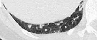
The pleura is usually
not seen in CT. It may be recognized as a dense line when, with a
pneumothorax, the lung retracts from the thoracic wall, as seen in
this case.
Lordotic view of the
apex of the lung. For different view of the apices of the lungs the
central beam is tilted either caudal or cranial.
Problems with wide
window setting in CT. With a wide window setting (left upper
image) the pronounced density due to fibrosis is hardly visible. With
a narrow window setting (right upper image) the marked density is
better perceptible. The heightened density is proven by the measured
values (image below). The flat white curve shows the shift of the
peak to lower values.
Wide and narrow
window settings in CT: Small nodules of sarcoidosis with wide
(right) and narrow window settings (left).
High Resolution Mode
of Computed Tomography. Left: CT with 8 mm slices thickness and
low kernel that does not enhance edges. Right: 2-mm thin slice
reconstructed with an edge-enhancing kernel ("HRCT").
Visualization of
vessels in thick (at right) and thin slices (at left) in CT. As a
thick slice captures more of an obliquely running vessel, the vessel
is depicted more longitudinally than in a thin slice, where only a
point shaped cut of the vessel is to be seen.
Rapid measurement
of minute densities in a nodule: window width is reduced to 2 HU,
i.e. black and white image results. The center value is changed to a
value where a first pixel in the area of interest bright up or the
last disappears. This center value represents the maximal density
value in the nodule.
The so-called "double
window technique" should not be utilized as the blurred borders
of the two windows may obliterate small pathologies.
Externally situated
materials on the chest may mimic pathologies. This may happen
with hair knots the proper positioning of which may be missed in
veiled women.
Pericardial fat may
blur the cardiac shape or even mimic a mass.
Misinterpreted
round shadow. On the lateral projection there is a round shadow
which can not be verified on the other projection. As the nodule is
supposed to be situated close to the mediastinum, a fluoroscopy is
recommended, but the nodule can not be localized. The keen
radiologist performs an extreme procedure: he switches the room light
on and stares at the patient who stands in front of him, arms up. In
the left arm pit there is a big wart.
Misinterpreted round
shadow in the right upper lung field. It is a pearl in knotted
hair. I learned of this nice case from ©Dr. Brauer
when we met in the Casamance, Senegal.
Supposed
metastases. In the p.a. projection of the left chest there are 2
rounded shadows. They could be localized outside the lung (right,
arrow) by fluoroscopy.
Supposedly right
paramediastinal space occupying lesion. A Medical doctor who
sports radiology (one stop shop!) did the x-ray of this lady. Duly he
transferred his patient for further investigations by CT. Instead,
the chest x-ray was repeated with hairs up and revealed a normal
x-ray.
Accessory cervical
rib at right side (arrowhead). Usually, an accessory cervical rib
can be diagnosed and discerned from the usual ribs by its straight
caudal direction. Lifting of the arm may result in compression of
vessels by the accessory rib. In the preoperative phase it may
compromise intubation.
Inspiration and
expiration: differences in the chest x-ray. In expiration a
normal heart may look as if the left heart is enlarged. The hili may
turn enlarged and blurred, as if there is cardiac congestion. The
lung is compressed which may result in misinterpretation of reduced
ventilation or consolidation.
Film adjacent
object. The nearer the depicted object is to the film (or
detector, in CR), the sharper it is delineated. In the right x-ray
the patient stands his right side to the film, on the left x-ray with
his left side. Question: on which side of the lung do you localize
the pulmonary lesion?
Cervical
lymphomas can be seen as soft tissue masses on the chest
x-ray.
Normal variants of the thoracic skeleton that may mimic pathologies (from Remy, modified):
Normal variants of the soft tissue of the chest that may mimic pathologies (from Remy, modified):
![]() (no consultations)
(no consultations)
17.8.00